■LCD■
1. 회로도를 본다.

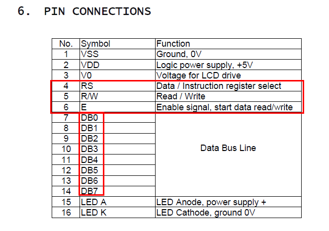
RS는 Instruction mode OR Data mode, E는 Enable 등.. 인걸 알 수 있다.
2. DataSheet를 본다 - 타이밍
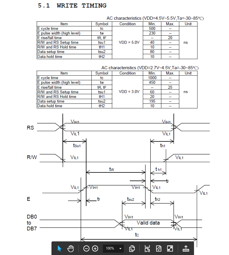
1. R/W : High, E : Low
2. RS : High or Low
3. R/W : High -> Low
------- 40nSec이상 delay
4. E : Low -> High
------- 150nSec이상 delay
5. Data Bus
------- 80nSec이상 delay
6. E : High -> Low
------- 10nSec이상 delay
데이터시트를 보면 Max가 없기에 Critical하게 꼭 맞춰줄 필요는 없어 보인다.
이러한 최소한의 딜레이가 필요하다. 그렇지 않으면 원하는 값으로 이루어지지 않음. Read mode에서는 RW쪽만 다르다.
3. Instructions 해석
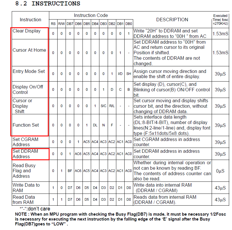
Note : Fiunction Set 5x11 dots는 4BIT일 경우만 사용 가능하다. 현재는 8bit,2-line,5x8로 set
그리고 실제 LCD는 5x7처럼 보이는데 커서가 1을 차지하여 5x8이다.
또한 Instruction후 딜레이 필요.
AND DDRAM은 DB7은 항상 set이여서 시작주소가 0x80이다. 1-Line과 2-Line이 bit수와 주소가 다르다.

#include "avr/io.h"
#include "avr/iom128.h"
#include "util/delay.h"
/*
	RS : Instruction mode VS Data mode?
	(LCD_controller VS LCD_data)
	E : Enable
*/
void LCD_controller(unsigned char control)
{
	_delay_ms(40);
	PORTG = 0x00; // clear.
	_delay_us(0.04); //RW & RS Setup time is 40ns min.
	PORTG |= 0x01; // G set.			Enable
	_delay_us(0.15); //Data Setup time is 80ns min.
	PORTA = control; // Data input.
	_delay_us(0.08); // valid data is 130ns min.
	PORTG = 0x0;// RS set. RW set. G clear.
	_delay_us(0.01);
}

void LCD_data(unsigned char Data)
{
	_delay_ms(1);
	PORTG = 0x04; //RS set. RW clear. G clear.
	_delay_us(0.04); //RW & RS Setup time is 40ns min.
	PORTG = 0x05; // E set.
	_delay_us(0.15); //Data Setup time is 80ns min.
	PORTA = Data; // Data input.
	_delay_us(0.08); // valid data min is 130ns.
	PORTG = 0x0; // RS clear. RW set. G clear.
	_delay_us(0.01);
}

void LCD_string(unsigned char address, unsigned char *ptr)
{
	int i=0;
	LCD_controller(address); // LCD display start position
	while(*ptr)
	{
		if(address+i == 0x90)
		LCD_controller(0xc0); // second line display

		LCD_data(*ptr);
		i++;
		ptr++;
	}
}

void LCD_initialize(void)
{

	/* 8bit interface mode */
	LCD_controller(0x38); // Function set. Use 2-line, display on.
	_delay_us(40); // wait for more than 39us.
	LCD_controller(0x0f); // Display ON/OFF Control. display,cursor,blink on
	_delay_us(40); // wait for more than 39us.
	LCD_controller(0x01); // Display Clear.
	_delay_ms(1.53); // wait for more than 1.53ms.
	LCD_controller(0x06); // Entry Mode Set. I/D increment mode, entire shift off
}

int main()
{
	DDRG = 0x07; // Control_bit
	DDRA = 0xff; // Data_bit

	LCD_initialize();
	LCD_string(0x80, "Hello World!!!! LCD TEST..12345678987654321"); // Start address is 0x80(0,0)


	while(1)
	{
	/*
	LCD_controller(0x1c);//화면 그대로 right
	LCD_controller(0x18);//화면 그대로 left
	_delay_ms(5000);
	*/
	}
	return 0;
}'kernel Driver' 카테고리의 다른 글
| [Atmega128]PWM(Buzzer) (0) | 2019.04.30 |
|---|---|
| GPIO를 이용한 I2C구현 (0) | 2019.04.24 |